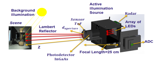
During the last decade, radio detecting and ranging (RADAR) technology evolved from the linear-frequency-modulated (LFM) systems developed in the 1970s to the orthogonal frequency-division multiplexing (OFDM) systems developed in the early 2000s. In the mid-2010s, systems were proposed that combined the radar principle with optical solutions developed for imaging and ranging tasks following a hyperspectral embedded systems approach. The idea was to profit on the one side from the possibility offered by RADAR systems to work in harsh environments using emitted radio waves and detect mainly metal objects placed far away (hundreds of meters or even kilometers) from the detection system with positioning spatial resolutions in tens of centimeters, even if there are non-metallic barriers such as, e.g., walls in between, and expand this possibility by using optical systems (e.g., light detecting and ranging –LIDAR- systems), using visible light active illumination, capable of generating 2D and 3D images of objects placed at much smaller distances from the detector, but allowing for much higher spatial resolutions (in the millimeter range). To reduce the atmospheric absorption of the emitted active illumination and increase the emitted optical power allowed for these systems that can correctly function even in harsh environments, we propose shifting the active illumination wavelengths from the visible range to the near infra-red (NIR) range, e.g., to 1550 nm. Lacking affordable image sensors fabricated in InGaAs technology, capable of detecting NIR radiation, in this work, we propose a hyperspectral imaging system using a very low power consuming single commercially available InGaAs photodiode to generate 2D images using the single-pixel imaging (SPI) approach based on compressive sensing (CS) and an array of NIR light emitting LEDs, combined with an 80 GHz millimeter band RADAR. The system is conceived to deliver a maximum radar range of 150 m with a maximum spatial resolution of ≤ 5 cm and a RADAR cross-section (RCS) of 10 – 50 m2, combined with an optical system capable of generating 24 fps video streams based on SPI generated images yielding a maximum ranging depth of 10 m with a spatial resolution of < 1 cm. The proposed system will be used in unmanned ground vehicle (UGV) applications enabling decision-making in continuous time. The power consumption, dimensions, and weight of the hyperspectral ranging system will be adjusted to the UGV-targeted applications.
RADAR SYSTEM
Due to the advantages offered by orthogonal frequency-division multiplexing (OFDM) radars in terms of bandwidth, controlled in these systems using multiple carriers, and in terms of ambiguity over LFM modulation, we propose using an OFDM radar imaging system with an operating frequency of 2.8 GHz together with the Software Defined Radios (SDR) tool, ETTUS B200 modules, and an antenna array. The proposed radar system was implemented and was finally tested on a UGV following the configuration. The scene scan is performed in front of the vehicle during the driving process. The RADAR imaging information is obtained from the radio signals reflected from the (primarily metallic) surrounding objects. Using the gathered information, a 2D image is generated, on the one hand, along the x-axis following a “cross-range” mode, following Eq. (1), where dmax is the distance to the object, the emitted radiation wavelength, and Leff the effective length of the antenna used for the emitter. On the other hand, the “down-range” is generated along the y-axis, defined using Eq. (2), where c is the speed of light, Nf is the frequency number, and Δf is the subcarrier spacing.
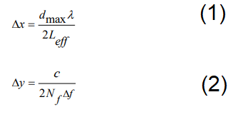

Fig.1. Photographs obtained from two test scenarios created for the performance evaluation of the OFDM RADAR system placed on top of a UGV (shown on both pictures on the left): (a) in the first test scenario, a cylindrical metallic object was placed at a distance of 90 cm in front of the UGV, which was then properly imaged by the RADAR, as it can be shown on the graph on the right; (b) in the second test-scenario, two objects to the one used in (a) were placed at precisely the same spot but 15 cm apart from each other, and were once again imaged adequately by the system, as shown on the graph on the right.
Comentarios