Millimeter wave is a particular class of radar technology that uses short-wavelength electromagnetic waves. The electromagnetic wave signal emitted by the radar system is reflected by other objects in the emission path, and by capturing the reflected signal, the radar system can determine information such as the distance, speed, and angle of the objects Localized within its field of view. Since the target echo distance information of the Linear-frequency-modulated continuous-wave (LFMCW) system radar can be simply processed using the Fast Fourier Transform (FFT). This was the most widely used modulation method and has been used for the most in-depth research on chirp continuous wave radar.

Fig.1. Block diagram of the FMCW radar system
The LFMCW radar system emits linear frequency modulation (FM) pulse signals and captures the signals reflected by objects in its emission path. Figure 1 is a simplified block diagram of the LFMCW radar system. The system working principle is as follows: first, the signal source generates a linear FM pulse transmitted by the antenna. The object reflects and modulates a reflected linear FM pulse captured by the receiving antenna. The mixer combines the transmitted and received signals to generate an intermediate frequency (IF) signal.
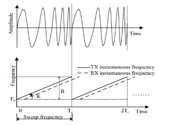
Fig.2. Amplitude of the linear FM pulse varying over time.
The mixer is used to mix the receiving end (RX) and transmitting end (TX) signals to generate an intermediate frequency (IF) signal. The output of the mixer contains two kinds of signals: the sum and the difference between the Rx and Tx chirp frequencies. In the FMCW radar system, the frequency of the emission signal increases linearly over time, and this type of signal is also known as the linear FM pulse signal, a function of the linear FM pulse amplitude that varies over time (see Fig. 2). The radar waveform used is the sawtooth wave, Tc is the sawtooth wave period, and B is the frequency modulation bandwidth.
Generation of 3D Images with the RADAR system
The radar signal received FMCW RADAR beat signal and model RADAR point reflectors in the scene (see Fig. 3b). From data simulation, we can synthesize RADAR heatmap top view (see Fig. 3c) and
front view (see Fig. 3d) applying 2D-FFT. From the RADAR heatmap font information, estimate the incident angles of the RADAR heatmap matrix and apply a Taylor series expansion over the model incidence reflection is possible to determine the point surface using 2D-FFT.
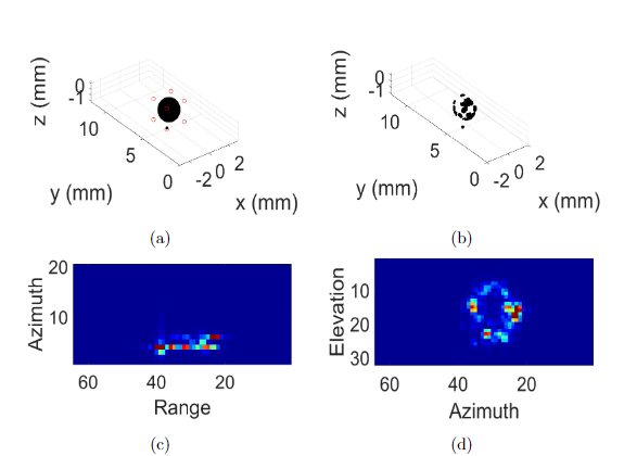
Fig.3. Simulation of the RADAR-generated image: (a) test object, (b) scanning surface obtained with radar, (c) Radar heatmap top view, and (d) Radar heatmap front view.
Generate images in the near/far field of objects with dimensions greater than 40 mm due to spatial resolution limitations of the RADAR system. In the test, defined as near field a distance of 25 cm (near-field<1m) and a far-field the 1.5 m (far-field>1m). The test object used was a sphere with a diameter of 65 mm, a cube of 45 x 45x45 mm, and a cylinder test object with dimension of 150 x 80 mm. In the test near-field, we generated the 2D image based on a heatmap (Fig.4).
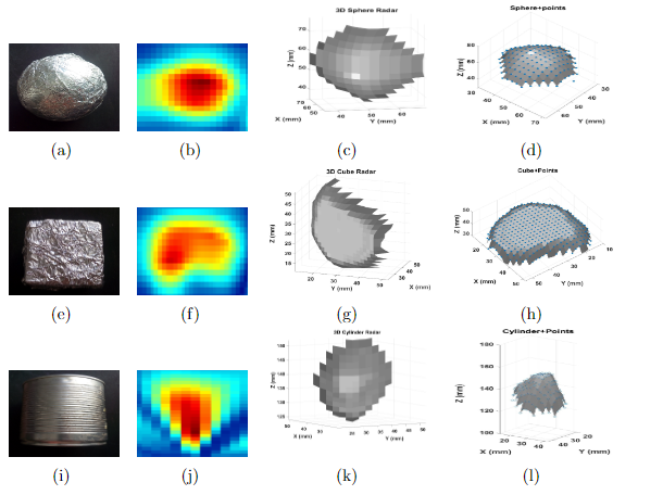
Fig.4. Reconstruction of RADAR images in the near-field of an object placed at 25 cm: (a-e-i) test object sphere with diameter 65 mm , cube 45 x 45 x 45 mm3, and a cylinder with 150x80 mm, (b-f-j) Radar image near-field of an object placed at 30 cm, (c-g-k) 3D image reconstruction , (d-h-l) 3D image reconstruction+points.
Comments