top of page

Research Blog

Buscar

In this article, we propose a method to be used for the reconstruction of single-pixel near-infrared (SPI-NIR) low-resolution 2D images using active illumination with a peak wavelength of 1550 nm that is based on Batch Orthogonal Matching (Batch-OMP) processing algorithms and a region definition in

the projection sequence of Hadamard illumination patterns using the genetic algorithm(GA). Different methods to generate Hadamard pattern sequences have been reported, mostly based on switching the illumination sequence on and off to improve the reconstructed image quality, thereby increasing the Structural Similarity Index Measure (SSIM) level and reducing the processing time. These methods are efficient for image sizes of>64x64virtual pixels, but for lower resolutions with small coherence areas Ach, the SNR level of the reconstructed image is very low, which makes other methods, such as those using the Zig-Zag or Hilbert filling curves for the scanning path, an option for the reconstruction of SPI-NIR low-resolution images. Because in the present application, we deal with low-resolution (size image 8 x 8 virtual pixels) SPI-NIR images, we present a solution to improve the obtained image quality (aiming at PSNR>10dBand SSIM>0.5) that is based on the use of a specific scanning path and a combination of a genetic algorithm to define the switching sequences of the Hadamard patterns, using Batch-OMP algorithm for image reconstruction in the processing time range between 20 and 35 ms.


Fig.1. Schematic diagram of Hadamard pattern generation using GA: (a) population with Hadamard parent patterns is generated to illuminate the object, (b) after the cost function measurement, these patterns are ranked using the matrix Hp, (c) each new pattern is created through changes in patterns using a mutation operation of the values, (d) the mutated offspring patterns replace the parent generation patterns. These steps are repeated in every generation.


Hadamard genetic algorithm (GA) for region-projection


To define the projection areas Ap, we start by dividing all the Hadamard N x N projection patterns required (for our application, the maximum required number of patterns is 64) into groups of N / 4, each containing a number of N / 16 patterns. These groups will be defined as projection areas and represented as a matrix Hp defined by Eq. (1). The matrix Hp is optimized to increase the quality of the reconstructed image while maintaining the processing time required <30ms, using between 20 and 80% of used Hadamard patterns. As an optimization strategy, a genetic algorithm method GA (see Fig.1) can be applied, in which the elements of the Hp matrix are encoded to form a binary vector (forming the GA initial population vector), where the ”1” elements define the groups without a change throughout the Hadamard sequence of patterns, and ”0” elements represent the groups of matrix elements that change the sequence of Hadamard patterns being sequentially switched ”on” and ”off.”


Definition of the most optimum projection of Hadamard patterns using illumination regions defined by the GA algorithm


To determine the most optimal sequence of Hadamard patterns to be projected to obtain the highest possible quality of the reconstructed images, as defined by the application of figures of merit PSNR>10dBand SSIM>0.5, it is necessary to define which projection sequences are necessary to be inverted to comply with our goal. To do this, GA was used to determine the most optimal ”on” and ”off” conditions of the different Hadamard matrix elements throughout the different pattern sequences in an evolutionary way. We used our data-set formed with images of spherical and square objects, using n x n pixel image sizes for the test.


Initially, we defined a Hadamard projection sequence of 64 patterns divided into 16 groups (see Fig. 2b) containing four elements of the projection sequence input element These elements were used to form the vector Vp that contains the matrix elements positions encoded in a binary form, and its dimensions are of 1 x 16. For the GA-based evaluation process, it was necessary to define an initial population of N = 8 divided into six parents. This initial population is an 8 x 16-pixel matrix containing random data. A fitness function was defined to evaluate the projection sequences, which will receive the Vp vector containing the positions of the different Hadamard matrix elements throughout the sequence of generated patterns corresponding to the population to be evaluated. We used the Zig-Zag, Hilbert, and Spiral scanning sequences to reconstruct a comparative study's single-pixel image of interest. (a) (b)


Fig 2: Generation of Ap sequence areas using GA algorithm: (a) Hadamard projection sequence of 64 patterns divided into 16 groups containing four elements of the projection sequence for the Ap projection area. (b) GA algorithm that evaluates the different switching on-off sequences in the Hadamard projection, using the vector Vp with binary positions defined for the different groups.


Foto del escritorCarlos Osorio

Walsh Hadamard Transform (WHT) is an orthogonal, symmetric, involutional, and linear operation used in data encryption, data compression, and quantum computing. The WHT belongs to a generalized class of Fourier transforms, which allows many algorithms developed for the fast Fourier transform (FFT) to work for fast WHT implementations (FWHT). This paper employs this property and uses a well-known parallel-pipeline FFT strategy for VLSI implementation to build parallel-pipeline architectures for FWHT. We apply the FFT parallel-pipeline approach on a Fast WHT and use the High-Level Synthesis (HLS) tool from Xilinx Vitis to generate an FPGA solution.

We also provide an open-source code with the basic blocks to build any model with any parallelization level. The parallel-pipeline proposed solutions achieve a latency reduction of up to 3.57% compared to a pipeline approach on a 256-long signal using 32-bit floating-point numbers.


Fig.1. Fast Walsh-Hadamard Transform dived on a vector of 8 samples.

The black dots perform the sum between the two input arrows. The

dashed lines invert the data sign, and the solid lines keep the data sign


In the last decade, vision systems have improved their capabilities to capture 3D images in bad weather scenarios. Several techniques exist for image acquisition in foggy or rainy scenarios that use infrared (IR) sensors. Due to the reduced light scattering at the IR spectra, it is possible to discriminate the objects in a scene compared with the images obtained in the visible spectrum. Therefore, in this work, we proposed 3D image generation in foggy conditions using the single-pixel imaging (SPI) active illumination approach in combination with the Time-of-Flight technique (ToF) at 1550 nm wavelength. For the generation of 3D images, we use space-filling projection with compressed sensing (CS-SRCNN) and depth information based on ToF. To evaluate the performance, the vision system included a designed test chamber to simulate different fog and background illumination environments and calculate the parameters related to image quality.


NIR-SPI System Test~Architecture


Fig.1. Sequence algorithm used to generate 2D/3D images.


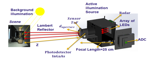
In this work, we propose an NIR-SPI vision system based on the structured illumination scheme depicted in Figure 1. Still, instead of using an SLM or a DMD to generate the structured illumination patterns, an array of 8 × 8 NIR LEDs is used, emitting radiation with the wavelength λ = 1550 nm. The NIR-SPI system architecture is divided into two stages: the first one controls the elements used to generate images by applying the already explained Fig.2. 3D NIR-SPI camera system developed

single-pixel imaging principle: an InGaAs photodetector (diode FGA015 @ 1550 nm), accompanied by an array of 8 × 8 NIR LEDs. Nevertheless, the spatial resolution of the objects in the scene is achieved by applying the Shape-From-Shading (SFS) method and the unified reflectance model, additionally applying mesh enhancement algorithms, is still very much away from the aimed resolution goal of below 10 mm at a distance of 3 m. Thus, four control spots were incorporated into the system illumination array, consisting of NIR lasers with controlled variable light intensity emulating an illumination sinusoidal signal modulated in time and four additional InGaAs photodiode pairs to measure the distance to the objects in the depicted scene with much higher precision, using the indirect Time-of-Flight (iTOF) ranging method (see Figure 3a). The second stage of the system is responsible for processing the captured signals by the photodiode module through the use of an analog-to-digital converter (ADC), which is controlled by a Graphics Processing Unit (GPU) (see Figure 2). The GPU unit (Jetson–Nano) generates the Hadamard patterns and processes the converted data by the ADC. The 2D/3D image reconstruction is performed using the OMP-GPU algorithm.


bottom of page